
Hello guys today I am going to share an intelligent idea of Modifying
general 24 pin SMPS to Dell optilex 3020/ 7020 / 9020 / T1700 SMPS
model i.e 8 pin.
This idea came to me when mine office Dell optilex 3020 SMPS was fired by surge voltage from short circuit. First, I tried with replacing another new SMPS of same model but due to unavailability in market I prefer of hacking 24/20 port SMPS which was easily available.
1st step:
Map the both SMPS pin configuration. I google the 24 pin SMPS pin configuration and found out but I couldn't found out the 8 pin SMPS configuration so I measured voltage and signal with multi meter from another working Optilex SMPS and found out those pin configuration.
2nd step:
After mapping the both SMPS pin configuration cut down listed 24 pin SMPS wires.
Then connect :
First is to use voltage shifter IC to shift voltage from +5v VSB to +12v VSB, which needs IC and other electronics so why to do it if there is simple trick. :)
Second is to use another +12v supply (yellow wire from 24 pin SMPS) as +12v VSB in 8 pin SMPS. But, doing only these can run your PC. Yes or No?
Answer is NO. The main hack lies here. To run a PC, firstly the SMPS must give the output to the PC_ON signal(green wire) and Voltage Standby (VSB) and after the PC_ON signal is grounded then only the SMPS gives output to other remainig pins. So the 12v (yellow wire) we have used only turns ON after the PC_ON signal is grounded. So in order to firstly output through the +12v pins short the PC_ON(green wire) signal to ground(black wire).
After doing this your connection must be as below :
4th step:
Finally now it is time to assemble and in your PC and test it.
After giving power to PC instantly your CPU and SMPS fan runs and you may worry. But, don't worry it is due to the short done with green and black wire. But your PC motherboard gets power only after you switch on the power button on CPU. So, you can happily use your PC.
Happy Hacking !
This article/tutorial is written by Sushan Baskota, ICTV DDC Panchthar. For feedback, please comment on the article below.
This idea came to me when mine office Dell optilex 3020 SMPS was fired by surge voltage from short circuit. First, I tried with replacing another new SMPS of same model but due to unavailability in market I prefer of hacking 24/20 port SMPS which was easily available.
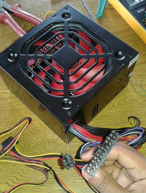
- 24 pin SMPS
Map the both SMPS pin configuration. I google the 24 pin SMPS pin configuration and found out but I couldn't found out the 8 pin SMPS configuration so I measured voltage and signal with multi meter from another working Optilex SMPS and found out those pin configuration.
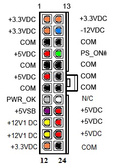
- 24 pin SMPS pin configuration
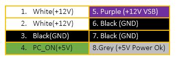
- Optilex 8 pin SMPS pin configuartion
After mapping the both SMPS pin configuration cut down listed 24 pin SMPS wires.
- 3 yellow wires (2 from 24 port and 1 from any other molex socket)
- 3 black wires
- 1 green wire (same for both SMPS)
- 1 grey wire (same for both SMPS)
Then connect :
- 2 yellow wires (24 pin) --> 2 white wires (8 pin)
- 3 black wires (24 pin) --> 3 black wires (8 pin)
- 1 grey wire (24 pin) --> 1 grey wire (8 pin)
First is to use voltage shifter IC to shift voltage from +5v VSB to +12v VSB, which needs IC and other electronics so why to do it if there is simple trick. :)
Second is to use another +12v supply (yellow wire from 24 pin SMPS) as +12v VSB in 8 pin SMPS. But, doing only these can run your PC. Yes or No?
Answer is NO. The main hack lies here. To run a PC, firstly the SMPS must give the output to the PC_ON signal(green wire) and Voltage Standby (VSB) and after the PC_ON signal is grounded then only the SMPS gives output to other remainig pins. So the 12v (yellow wire) we have used only turns ON after the PC_ON signal is grounded. So in order to firstly output through the +12v pins short the PC_ON(green wire) signal to ground(black wire).
After doing this your connection must be as below :
- 2 yellow wires (24 pin) --> 2 white wires (8 pin)
- 3 black wires (24 pin) --> 3 black wires (8 pin)
- 1 grey wire (24 pin) --> 1 grey wire (8 pin)
- 1 yellow wires (24 pin) --> 1 purple wire (8 pin)
- Short green and black wire (24 pins)
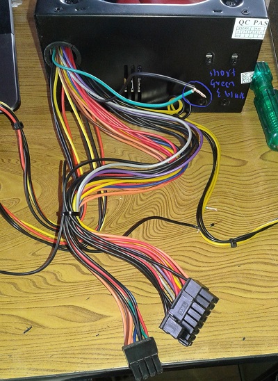
- Green and Black wire Short.
Finally now it is time to assemble and in your PC and test it.
After giving power to PC instantly your CPU and SMPS fan runs and you may worry. But, don't worry it is due to the short done with green and black wire. But your PC motherboard gets power only after you switch on the power button on CPU. So, you can happily use your PC.
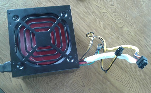
- Final SMPS
This article/tutorial is written by Sushan Baskota, ICTV DDC Panchthar. For feedback, please comment on the article below.
0 comments:
Post a Comment